
ME Spark Gap Tesla Coil 1


Introduction
As my first steps into high voltage and tesla coils in particular, this SGTC was a fantastic introduction. The lesser electrical and mechanical complexity compared with other tesla coil variants makes a SGTC way easier to build. I recommend anyone who wants to follow the steps of high voltage builders and hobbyists to first build a SGTC. The build is composed of cheaper or secondhand components. Because of this some of the materials used are not quite ideal because of increased losses in the system. Most of the build material is also wood, which is by far not ideal for a tesla coil because of the danger of fire. Fortunately, this tesla coil is rather small and the non ideal material characteristics can be avoided by bigger gaps between conductors.
Specifications
| Build year | 2016 |
| Supply | 230 Vac to a 10kV/50mA high voltage Neon transformer |
| Primary coil | Spiral coil, 100 mm inner diameter, 7 mm copper tube, 7 mm spacing, 5 windings (tapped at ~4) |
| MMC | 22x 150nF/1250Vdc in series for 150nF/27.5kV |
| Secondary coil | 0.5 mm enamelled wire. 600 windings on 300 mm length, 60 mm diameter |
| Topload | 100 mm Sphere |
| Spark length | 300 mm |
Schematic & Function
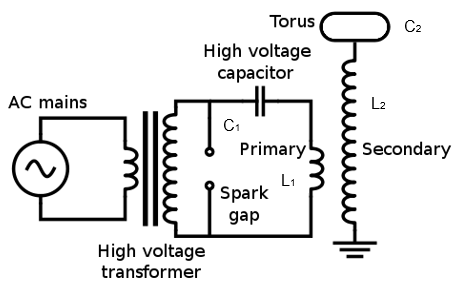
See SGTC for more information on the function of a Spark Gap Tesla Coil. Typically an old microwave transformer can be used as a cheap alternative to a high voltage Neon transformer. These transformers come at around 2 kV. Make sure to keep the spark gap distance variable to trim the tesla coil for longer sparks.
Calculations
The teslatool was used for the calculations of the build. The values listed below were used as input for the equations.
Primary coil:
- Inner diameter: 100
- Spacing between windings: 7
- Wire diameter: 7
- Number of windings: 5
- Winding angle: 0
- Height above secondary coil: 20
Secondary coil:
- Coil diameter; 60
- Spacing between windings: 0
- Enamelled wire diameter: 0.5
- Winding lenght: 300
- Torus thickness: 0
- Outer diameter of torus: 100
The resulting primary coil inductance is 4.96µH and secondary coil inductance is 3.91 mH. Together with a total secondary capacitance of 10.44 pF this equals a resonance frequency of 787.74 kHz. As both resonance circuits should have the same frequency for an optimal energy transfer and amplification, the primary frequency needs to be the same. This is done by choosing the primary capacitor accordingly and build the primary coil variable. The necessary primary capacitor is 8.82 nF.
Construction
The construction was done with a limited budget, so rather cheap material was used. This results in more of a tinkered build, which works nonetheless. Wood was used as basic construction material which not ideal because of the its characteristic to burn when presented to high temperature contacts (more on that later). With enough spacing everywhere, wood is still usable for fast construction.
MMC
For the primary capacitors voltage capabilities need to be higher then the 10 kV from the Neon transformer. Typically for electrolyte capacitors, the voltage capabilities should be 33% higher. For have enough margin, this seemed to be a good starting point, so ~13kV is necessary. The chosen capacitors are “Manf. Nr.” with Uac of 600 V and 150 nF. With 22 capacitors in series, the resulting MMC has 6.81 nF at 13.2 kV. With various deviations in the coil and variable primary inductance, this deviation in capacitance is completely fine.
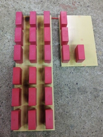
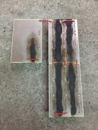
Because the capacitors were soldered on a breadboard pcb, there was a worry for arcing between rails. To prevent this, the rails between the capacitor rows were removed with a torch. It definitely does not look good, but it works.
The MMC holds potential dangerous charges at the shutdown of the coil and needs to be discharged. For capacitors with big capacitance and/or high voltages it’s always better to be safe then sorry. Across each of the 22 capacitors, a 2MΩ resistor is soldered. As a result the MMC is discharged in about 1.5 seconds.
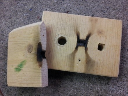
Spark gap
The spark gap was built using steel threaded rods and copper tubing to form two variable gaps. This was done for easy wiring. Efficiency could be massively increased by only using highly conductive material instead of steel and reducing the build to one gap. Variable gaps increase the ease of coil tuning.
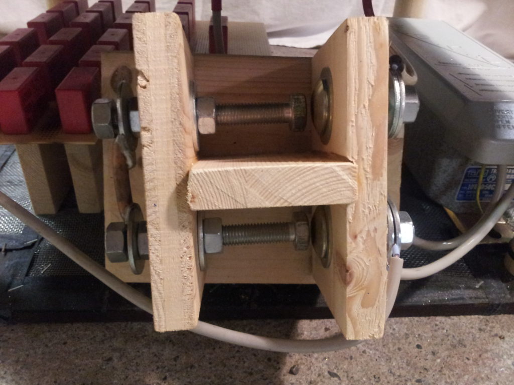
The washers at the spark gaps were placed too close. With increased spark gap distance, more energy was built up. This resulted in the arcs to take the way of least resistance through the wooden shielding panel and caused a small fire. Smaller washers were used and distance between the gaps was increased.
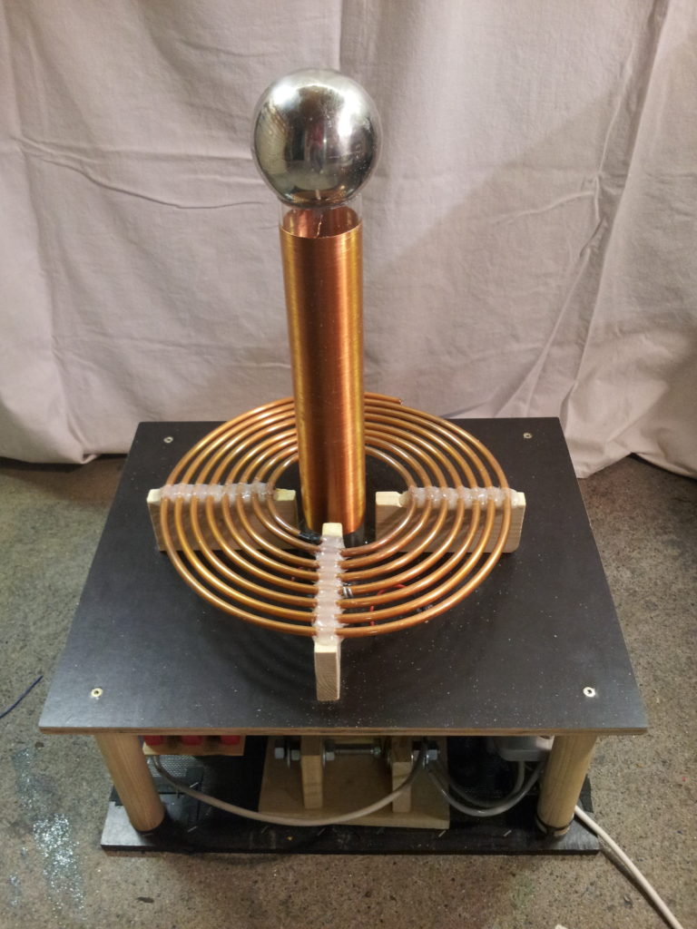
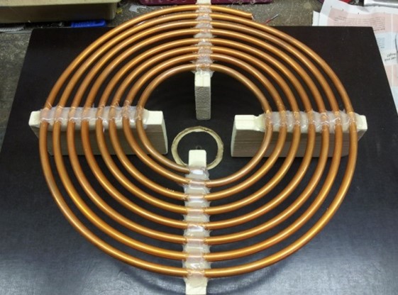
Primary coil
The primary coil is hand-wound from 7 mm copper tubing. Placeholders were put on the wooden supports to hold the tube in place. To prevent shifting, the tube was fixed in place by hot glue. Wooden supports and hot glue are by no means good build materials for the primary coil as the inductance can become hot enough to melt or burn the material. Because of short run times and small coil build, the inductance does not get hot enough to destroy the supports. The inductance was tapped in the innermost winding and at the appropriate length to maximize synchronization.
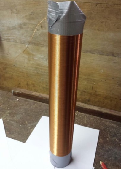
Secondary coil
The secondary coil was wound with 0.5 mm diameter enamelled copper wire. With about 600 turns, the 300 mm long inductance was hand-wound on a plexiglas tube with a diameter of 60 mm. The coil was covered with multiple layers of clear varnish to increase the insulation. High insulation is necessary to prevent arcing between the primary coil and secondary coil as well as topload and secondary coil.
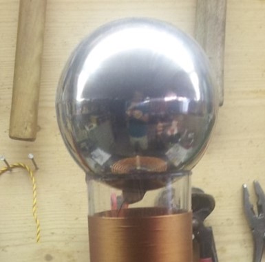
Secondary capacitor
A 100 mm decorative steel ball was used as topload. The conductive and smooth surface characteristics of the ball are ideal to make a secondary capacitance. The smooth surface enables arcs to erupt from the ball in any direction. A nail can be taped to the surface and be used as a breakout point to control the direction of the sparks.
Tuning
There are normally two places to tune a standard SGTC. The primary coil tapping point and the spark gap distance. The primary coil tuning is used to synchronize the primary resonance circuit with the given secondary resonance circuit. The secondary inductance and capacitance are constant values which determine a secondary resonance frequency. In theory, the energy transmission from primary circuit to secondary circuit is maximized when the resonance frequency is equal in both circuits. However, an arc from the topload adds additional capacitance to the secondary circuit which in turn lowers the ideal synchronized resonance frequency. The capacitance change varies depending on the length of the arc and if the arc strikes anything. Thus, ideally the primary circuit should then be tuned a bit lower then the secondary circuit. This results in an initially out of tune tesla coil with increasing performance after the arc forms. The primary coil can be tuned in two ways. Try and error or measuring as described here.
Conclusion
There is a steep learning curve for building a tesla coil. A SGTC was ideal as an introduction as the schematic and build is not too complex. There is lot of room to improve the build with less conductor resistance, better tuning and robuster build material. Either way I am happy with the results. The build quality is sufficient for an initial design and with my limited knowledge at a tender age. I will probably not improve the design as there are more complex and enjoyable coil builds to tackle like a DRSSTC.
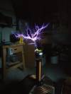
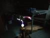
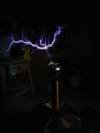
Demonstration
When a lightbulb is placed at the breakout point of a Tesla coil, it looks similar to a plasma-ball. This only really works for small Tesla coils if the voltage is not too high. Because of around 300mm arc lenght the arc at my coil do not stay confined inside the bulb and the following effect occurs.