ME Dual Resonant Solid State Tesla Coil 1
Introduction
This was the first DRSSTC I have built. The increased complexity resulted in more tinkering then initially planned. Nevertheless, the result were satisfactory with 1200 mm musical arcs. The build was started in late 2017, but because of studies I never finished it until 2021.
Specifications
| Build year | 2021 |
| Supply | 230 Vac |
| Primary coil | Spiral coil, 250 mm inner diameter, 7 mm copper tube, 7 mm spacing, 8 windings (tapped at ~4) |
| MMC | 22x 150nF/1250Vdc in series for 150nF/27.5kV |
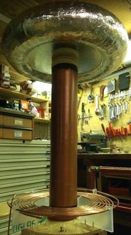
| Secondary coil | 0.4 mm enamelled wire. 2000 windings on 300 mm length, 60 mm diameter |
| Topload | 700 mm diameter torus with 150 mm ring |
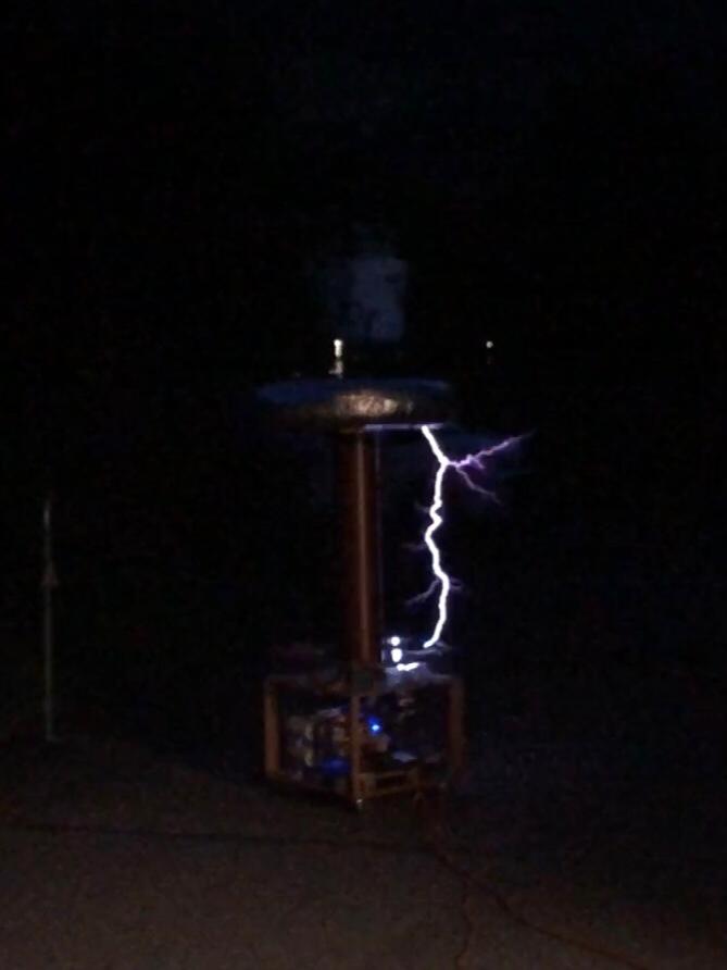
| Spark length | 1’200 mm |
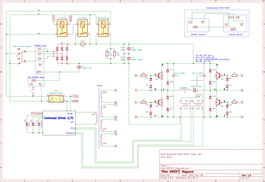
Schematic & Function
A DRSSTC has a complex circuit with many possibilities to expand with additional drivers, gadgets and safety measures. Below, only the power circuit with the most important components is shown. The DC power bus is switched with IGBTs to oscellate a resonant circuit. In parallel to the primary coil and capacitor there is a secondary coil with a topload which is not depicted in the schematic. The frequency and current of the primary circuit gets measured with self-wound current transformers and are used to drive the IGBTs to reach zero-current switching.
Calculations
The teslatool was used for the calculations of the build. The values listed below were used as input for the equations.
Primary coil:
- Inner diameter: 250
- Spacing between windings: 7
- Wire diameter: 7
- Number of windings: 5
- Winding angle: 0
- Height above secondary coil: 0
Secondary coil:
- Coil diameter: 150
- Spacing between windings: 0
- Enamelled wire diameter: 0.4
- Winding lenght: 800
- Torus thickness: 150
- Outer diameter of torus: 800
The resulting primary coil inductance is 12.2 µH and secondary coil inductance is 102.58 mH. Together with a total secondary capacitance of 48.19 pF this equals a resonance frequency of 73.105 kHz. As both resonance circuits should have the same frequency for an optimal energy transfer and amplification, the primary frequency needs to be the same. This is done by choosing the primary capacitor accordingly and build the primary coil variable. The necessary primary capacitor is 388.19 nF.
Construction
The construction was done with a limited budget. Mostly cheaper or second hand material was used which results in more of a tinkered build. After the initial construction the coil was rebuilt a second time because of issues with the electronics and the need of continued maintenance to repair the build.
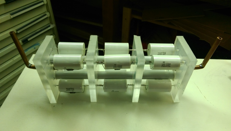
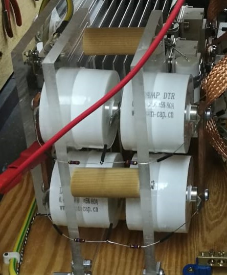
MMC
The initial version of the MMC consisted of four parallel strands of three 150 nF, 2 kV capacitors (942C20P15K-F) in series. The resulting 450 nF, 6 kV MMC was soldered to fixed copper tubing as conductor. At each end of the tubing a cable lug was crimped on. This MMC worked perfectly fine and was only reworked because I wanted to try the newly discovered dawn-cap capacitors and I redesigned the coil electronics anyway. The new MMC consisted of two parallel strands of two 400 nF, 6 kV capacitors (DTR6000K0.40) in series which resulted in 400 nF, 12 kV. The dawn-cap capacitors have a threded M6 connector which is ideal for busbar connection. Also the connections between each capacitor in series can easily done by a short threaded rod.
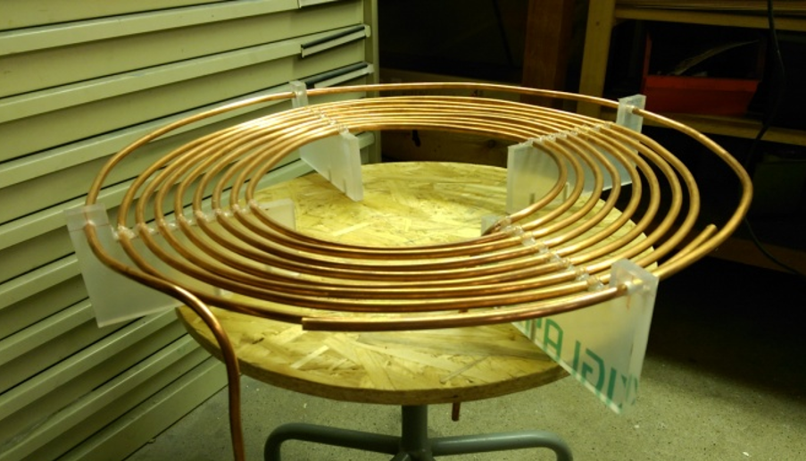
Primary coil
The primary coil was wound using 7 mm copper tubing on 10 mm acrylic stands. Acrylic is not an ideal material because of its low temperature tolerance. As of now, the tolerance was enough for this coil as tests showed no deformation even after long usage. The primary coil was built with a conservative approach to tuning. 5 turns were calculated, 8 built and in the end the tap was set at around 4 turns. Only the base plate on which the acrylic stands are mounted was modified in the new version.
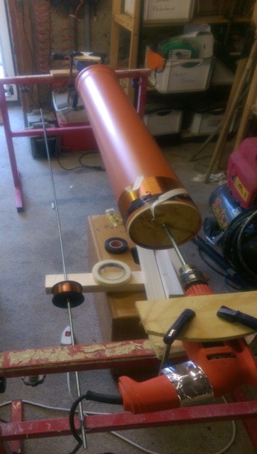
Secondary coil
The winding of the secondary coil was shortened considerably with a bit of preparation. I built an improvised lathe using a drill, a threaded rod and two wooden plates the size of the PVC tubes. The With this lathe the winding was done within an hour. The drill switch was taped to a slow rotation. As the hands are occupied with keeping the wire steady, a power strip was then used to switch the drill on and off with a foot. The turns were fixed in position with tape from time to time to prevent unrolling of the wire. At the end the ends were taped neatly and the coil was covered in a few layers of clear varnish to increase isolation. The secondary coil stayed the same for both versions.
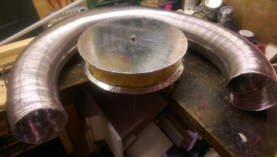
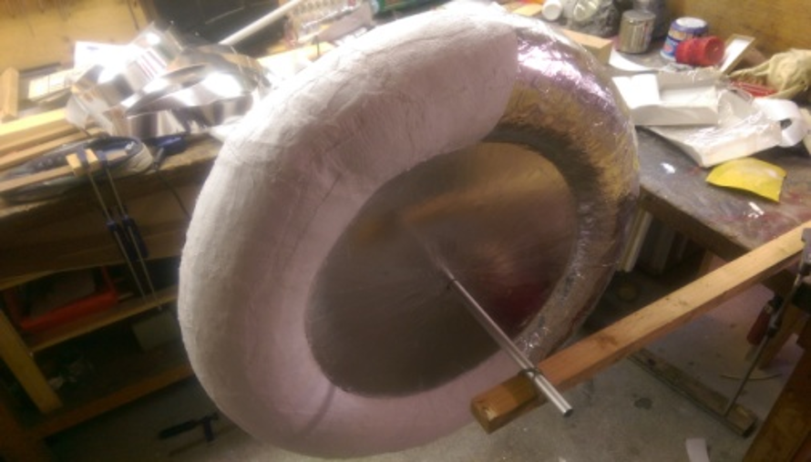
Secondary capacitor
An aluminium flex pipe was fixed between two wooden plates covered in aluminium tape using an elastic band. After the realization that the flex pipe is delicate to transport and store, the aluminium pipe was covered in a layer of paste to increae durability. After curing the build was covered in a layer of aluminium tape to create a smooth conducting surface. The topload stayed the same for both versions.
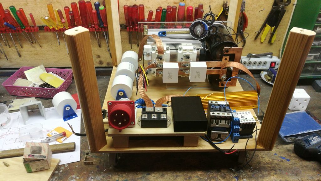
Conclusion version 1
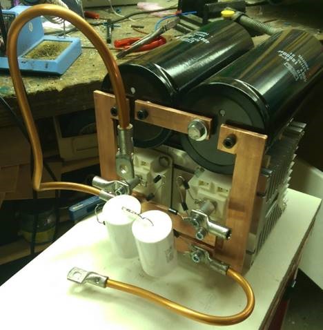
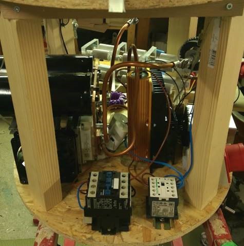
This initial build had a very compact design with allowed all electronics to fit on a small area. Because the build is heavily tinkered, there are many small components for assembly. For example, there are many TVS diodes and copper tube conductors that need to be placed and then awkwardly screwed on the IGBT to assemble as seen in the left image. This increased the necessary time for maintenance endlessly. A huge disadvantage was also the difficulty to access components, as many are placed in the middle of the heatsinks. This can be seen in the right image. Because of continued problems with the driver which resultet in destroyed IGBTs, this build was ultimately scrapped for a more spacious build.
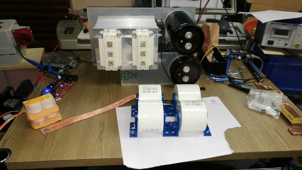
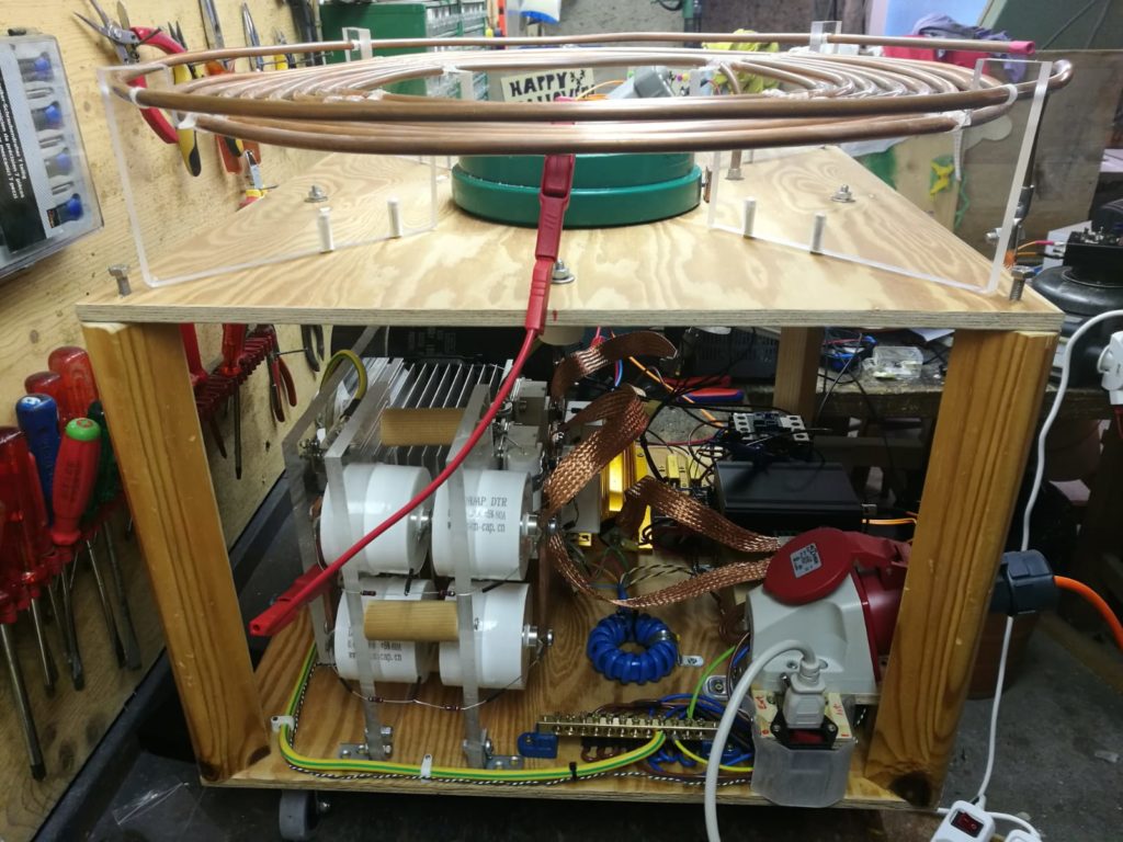
Conclusion version 2
The rebuild had a similar complexity with the number of small components but was much more spacious. As such all components are better accessable for the initial build and maintenance. The coil was initially designed to be powered by 400 V. The OCD of the driver triggered very fast at voltages of higher then 230 V so the coil was only ever supplied with 230 Vac. Normally, braided copper wire is used for ground connections. However it works just as well for busbar connections. The braided cable I had access to was way too long for the build, so the connection had to be aligned and fixed to prevent short circuits.
Demonstration